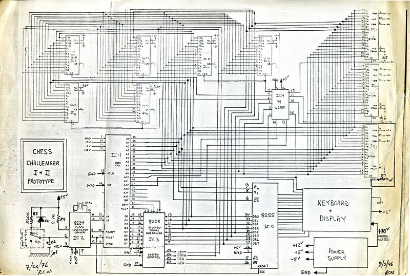
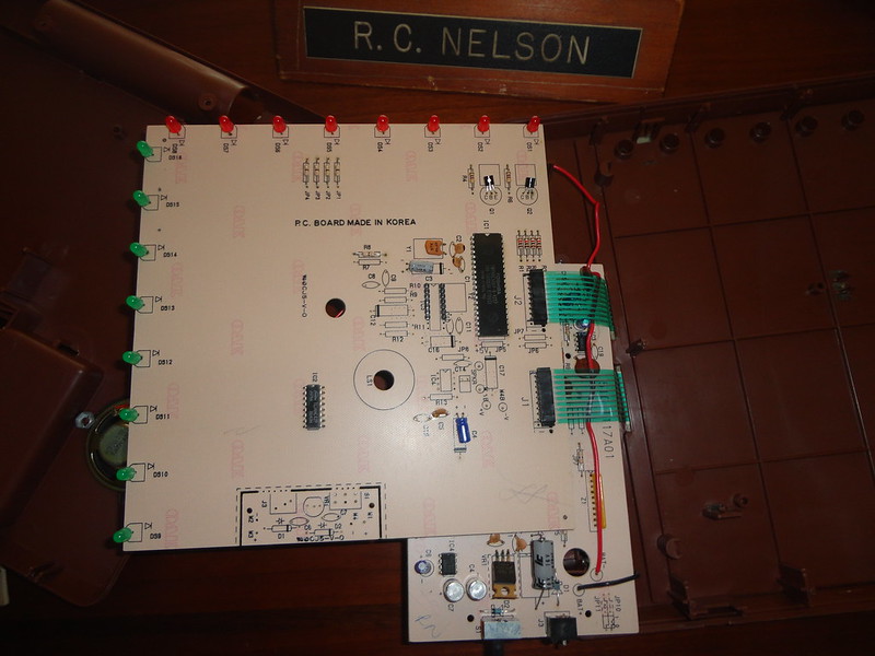
One can notice the great use of NEC integrated circuits, instead of Intel.
NEC was just getting into the 8080 chip business and we were their first large customer, so their pricing was attractive compared to Intel.
Moderators: Harvey Williamson, Steve B, Watchman
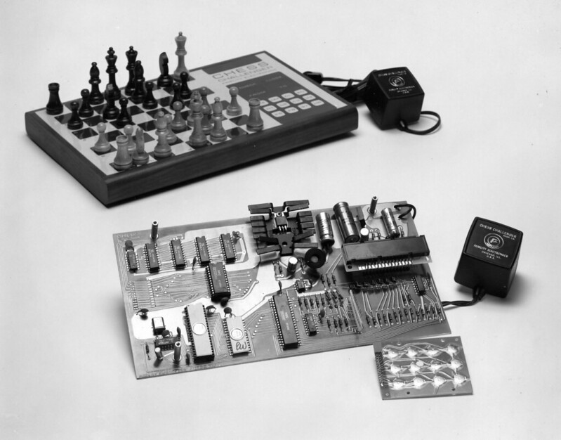
Stan Bialek is the name of the young mechanical designer (he never got a degree but he was very talented). He took my sketch and made the first prototype.Larry wrote:Interesting. It does remind me of something that I thought I'd ask while
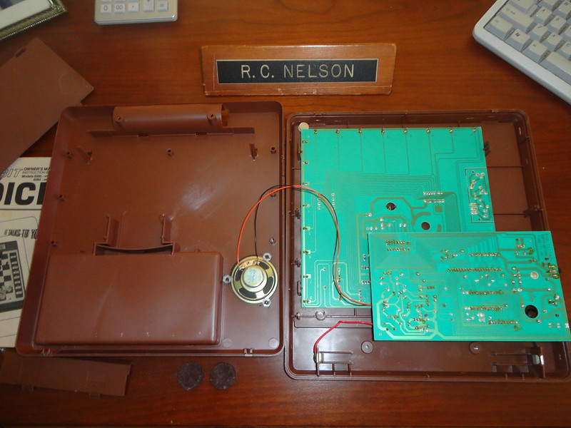
you are here. What was the logic behind securing the insides of the
original chess challengers by fixing the back plate with brads, not screws?
It meant that the back plate had to be destroyed to get it off. I think they
also used glue in addition to the screws. I can understand that it made
it hard for unqualified wannabees to frig with the circuit board, but it also
made it hard for service professionals, no?
Here we are about four decades on, and the early CC1/CC3's are starting
to develop a problem. Oxidation on the control panel buttons contact
surfaces is breaking the circuit and making them inoperable. You know
the problem is starting when you have to press a control button repeatedly,
and soon after even that does'nt work. My CC1 has this problem, and they
all soon will. I can get around the problem temporarily by putting the CC1
in the refrigerator for a half hour or so and it then works. But after it
returns to room temperature the problem returns.
Your thoughts on this please Ron?
warm regards ...Larry

The article written by Alan Wray can be found at the HP museum:In accordance with one embodiment of the present invention, evaluation of possible responsive moves and selection of the responsive move to be made by the system is achieved by use of evaluation criteria such as is described in an article entitled "A Chess Playing Program For The 9810A" by Alan A. Wray in a Hewlett-Packard publication which program is available from Hewlett-Packard upon request. This program was modified to correct apparent errors and to render it compatible with components incorporated as part of the present system.